AUTOMATION-->COMMUNICATION PROTOCOLS
I2C-INTER INTEGRATED CIRCUIT
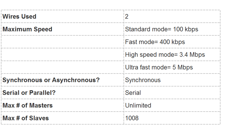
I2C (Inter-Integrated Circuit, eye-squared-C), alternatively known as I2C or IIC, is a synchronous, multi-master, multi-slave, packet switched, single-ended, serial communication bus invented in 1982 by Philips Semiconductors. It is widely used for attaching lower-speed peripheral ICs to processors and microcontrollers in short-distance, intra-board communication. It is a address oriented protocol.
Working of I2C Communication Protocol :
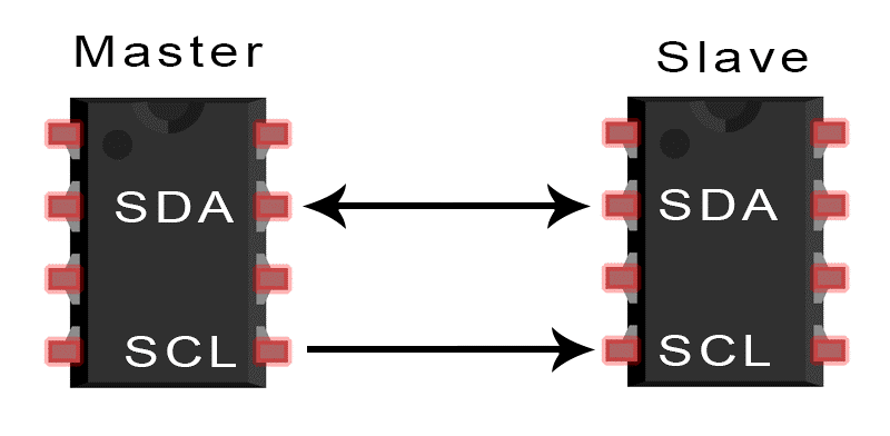
It uses only Two bi-directional open-drain lines for data communication called SDA and SCL.
Both these lines are pulled high.
Serial Data (SDA) – Transfer of data takes place through this pin.
Serial Clock (SCL) – It carries the clock signal.
I2C operates in 2 modes –
- Master mode
- Slave mode
Each data bit transferred on SDA line is synchronized by a high to the low pulse of each clock on the SCL line.
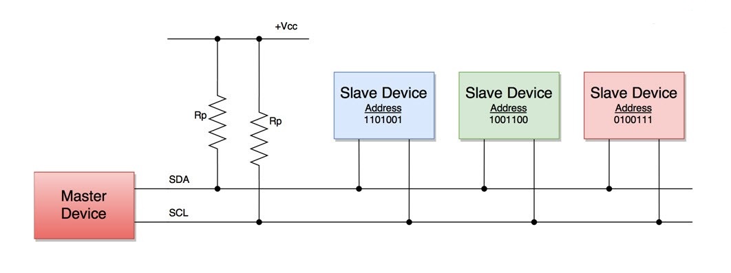
According to I2C protocols, the data line can not change when the clock line is high, it can change only when the clock line is low. The 2 lines are open drain, hence a pull-up resistor is required so that the lines are high since the devices on the I2C bus are active low. The data is transmitted in the form of packets which comprises 9 bits. The sequence of these bits are –
1. Start Condition – 1 bit
2. Slave Address – 8 bit
3. Acknowledge – 1 bit
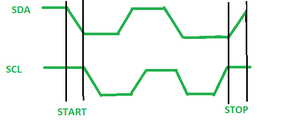
Start and Stop Conditions :
START and STOP can be generated by keeping the SCL line high and changing the level of SDA. To generate START condition the SDA is changed from high to low while keeping the SCL high. To generate STOP condition SDA goes from low to high while keeping the SCL high.
Repeated Start Condition :
Between each start and stop condition pair, the bus is considered as busy and no master can take control of the bus. If the master tries to initiate a new transfer and does not want to release the bus before starting the new transfer, it issues a new START condition. It is called a REPEATED START condition.
Read/Write Bit :
A high Read/Write bit indicates that the master is sending the data to the slave, whereas a low Read/Write bit indicates that the master is receiving data from the slave.
ACK/NACK Bit :
After every data frame, follows an ACK/NACK bit. If the data frame is received successfully then ACK bit is sent to the sender by the receiver.
ADDRESSING:
The address frame is the first frame after the start bit. The address of the slave with which the master wants to communicate is sent by the master to every slave connected with it. The slave then compares its own address with this address and sends ACK.
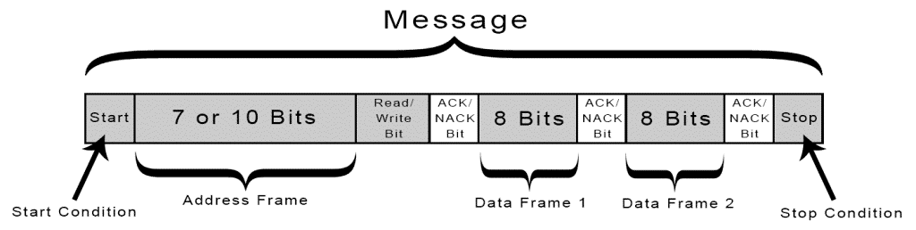
I2C Packet Format :
In the I2C communication protocol, the data is transmitted in the form of packets. These packets are 9 bits long, out of which the first 8 bits are put in SDA line and the 9th bit is reserved for ACK/NACK i.e. Acknowledge or Not Acknowledge by the receiver.
START condition plus address packet plus one more data packet plus STOP condition collectively form a complete Data transfer.
STEPS OF I2C DATA TRANSMISSION
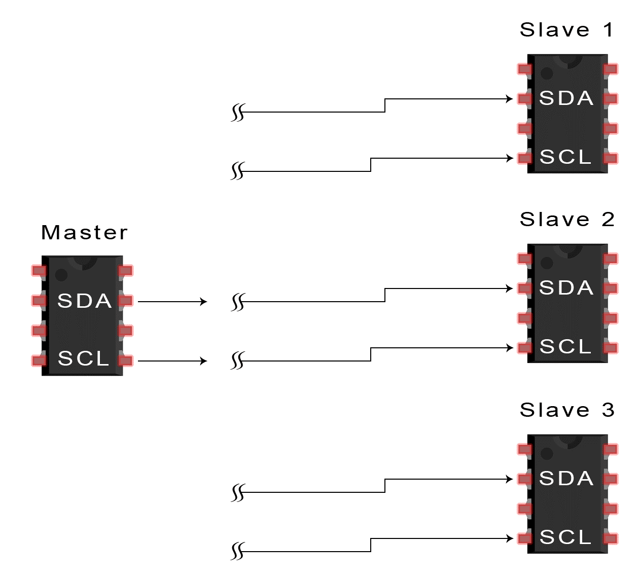
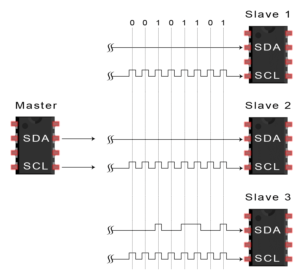
1. The master sends the start condition to every connected slave by switching the SDA line from a high voltage level to a low voltage level before switching the SCL line from high to low:
2. The master sends each slave the 7 or 10 bit address of the slave it wants to communicate with, along with the read/write bit:
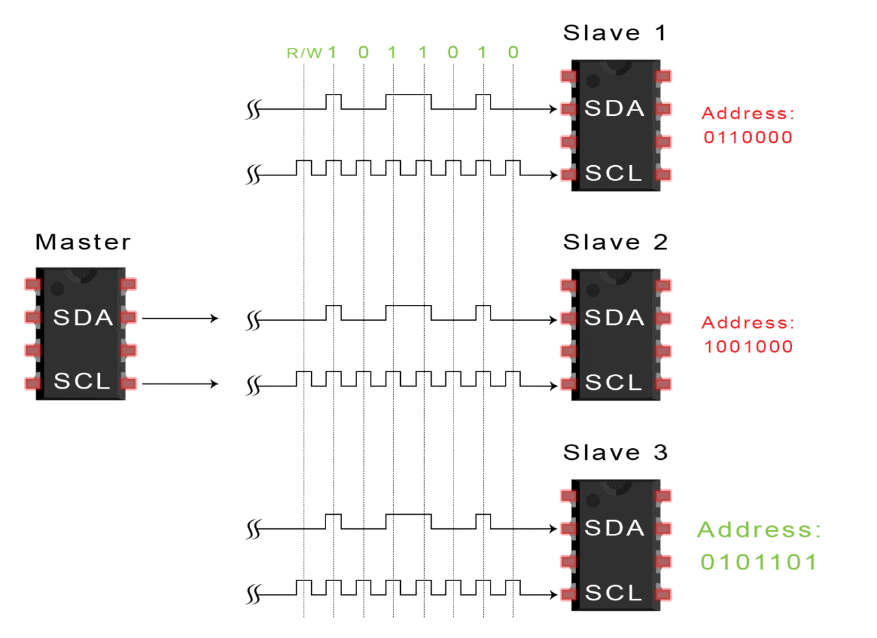
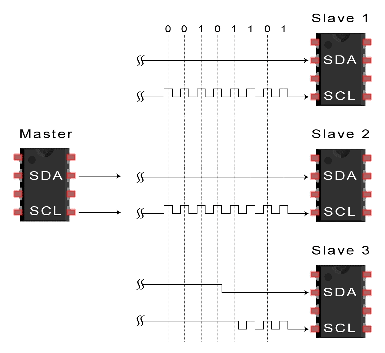
3. Each slave compares the address sent from the master to its own address. If the address matches, the slave returns an ACK bit by pulling the SDA line low for one bit. If the address from the master does not match the slave’s own address, the slave leaves the SDA line high.
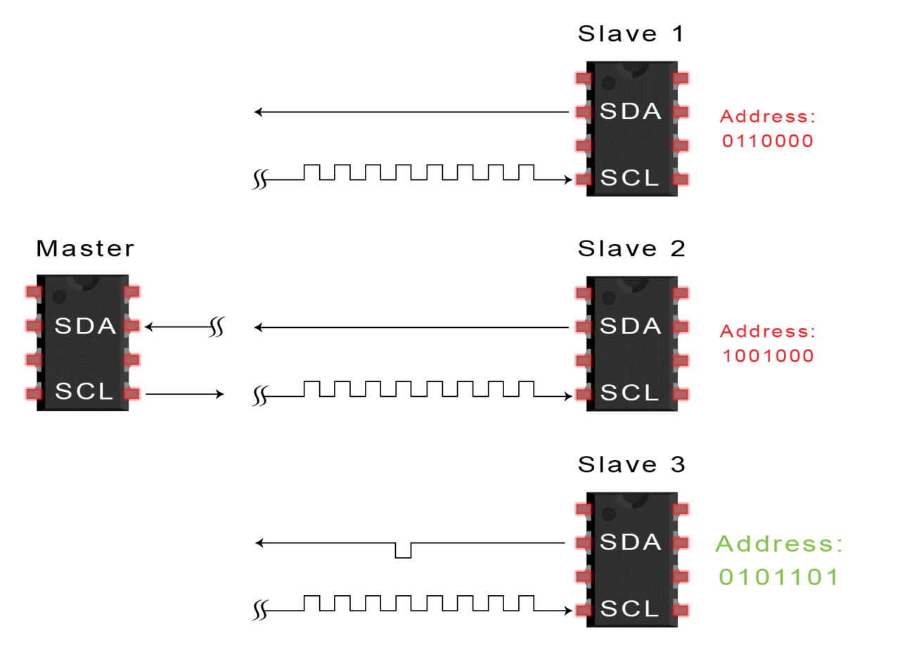
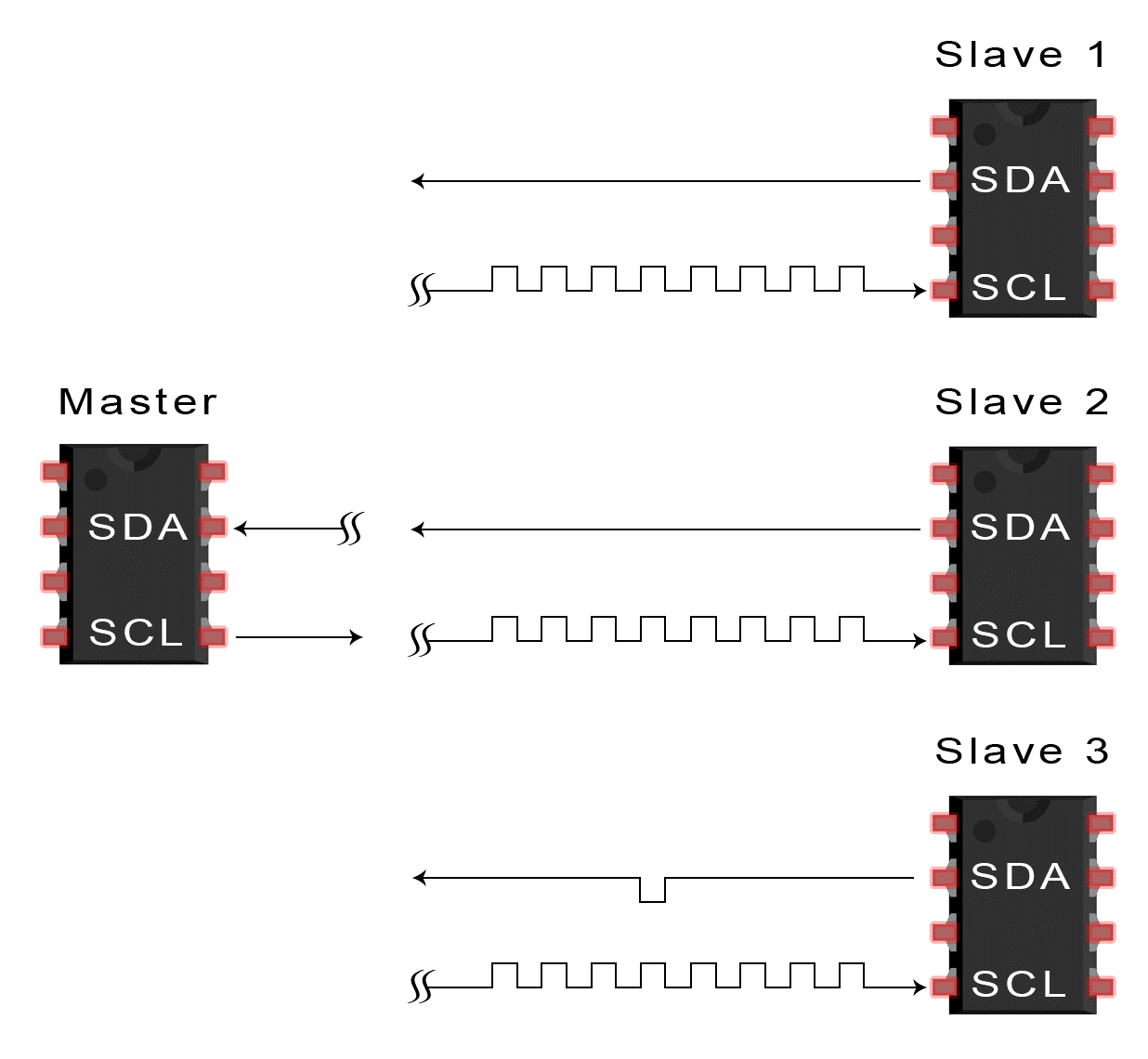
4. master sends or receives the data frame
5. After each data frame has been transferred, the receiving device returns another ACK bit to the sender to acknowledge successful receipt of the frame:
6. To stop the data transmission, the master sends a stop condition to the slave by switching SCL high before switching SDA high:
Features of I2C Communication Protocol :
• Half-duplex Communication Protocol –
Bi-directional communication is possible but not simultaneously.
• Synchronous Communication –
The data is transferred in the form of frames or blocks.
• Can be configured in a multi-master configuration.
• Clock Stretching –
The clock is stretched when the slave device is not ready to accept more data by holding the SCL line low, hence disabling the master to raise the clock line. Master will not be able to raise the clock line because the wires are AND wired and wait until the slave releases the SCL line to show it is ready to transfer next bit.
• Arbitration –
I2C protocol supports multi-master bus system but more than one bus can not be used simultaneously. The SDA and SCL are monitored by the masters. If the SDA is found high when it was supposed to be low it will be inferred that another master is active and hence it stops the transfer of data.
• Serial transmission –
I2C uses serial transmission for transmission of data.
• Used for low-speed communication.
Registers Used for I2C
1.MSSP Status Register (SSPSTAT)
2.MSSP Control Register 1 (SSPCON1)
3.MSSP Control Register 2 (SSPCON2)
4.Serial Receive/Transmit Buffer Register (SSPBUF)
5.MSSP Shift Register (SSPSR) – Not directly accessible.
6.MSSP Address Register (SSPADD)
SSPSTAT – MSSP Status Register
This register is the status register of the MSSP Module. The lower six bits of the SSPSTAT are read-only. The upper two bits of the SSPSTAT are read/write.
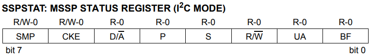
BF: This is the Buffer Full status bit. In the transmit mode this bit will set when we write data to SSPBUF register and it is cleared when the data is shifted out. In the receive mode, this bit will set when the data or address is received in the SSPBUF register and it is cleared when we read the SSPBUF register.
UA: This is the Update Address bit and is used only in 10-bit address mode. It indicates that the user needs to update the address in the SSPADD register.
R/W: This is the Read/Write bit information. In the slave mode, it indicates the status of the R/W bit during the last address match. In the master mode, 1 indicates that transmit is in progress and vice versa.
S: This bit indicates that a Start bit is detected last and it will be cleared automatically during Reset.
P: As above, this bit indicates that a Stop bit is detected last and it will be cleared automatically during Reset.
D/A: This is the data or addresses indicator bit and it is used only in slave mode. If it is set, the last byte received was data otherwise it will be addressed.
CKE: Setting this bit enables SMBus specific inputs. SMBus is another bus similar to I2C, which is compatible with each other.
SMP: Setting this bit disables slew rate control and vice versa.
SSPCON1 – MSSP Control Register 1
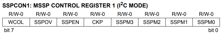
SSPM0 ~ SSPM3: These are synchronous serial port mode select bits.
1111 = I2C Slave mode, 10-bit address with Start and Stop bit interrupts enabled
1110 = I2C Slave mode, 7-bit address with Start and Stop bit interrupts enabled
1011 = I2C Firmware Controlled Master mode (Slave Idle)
1000 = I2C Master mode, clock = FOSC/(4 * (SSPADD + 1))
0111 = I2C Slave mode, 10-bit address
0110 = I2C Slave mode, 7-bit address
CKP: This is the SCL clock release control bit. It is used only in slave mode. Setting this bit releases the clock. If zero, it holds the clock (clock stretch).
SSPEN: This is the synchronous serial port enable bit. Setting this bit enables the serial port.
SSPOV: This is receiving an overflow indicator bit. If this bit is set during receive mode, it indicates that a byte is received while SSPBUF is holding the previous value. And it has no application in transmit mode. We must clear this bit in software.
WCOL: It is the write collision detect bit. If this bit is set during master to transmit mode, it indicates that a write to SSPBUF register was attempted when I2C conditions were not valid for a transmission to be started. And if it is set during a slave to transmit mode, it indicates that the SSPBUF register is written when it is transmitting the previous word. We must clear this bit in software.
SSPCON2 – MSSP Control Register 2
The SSPCON2 register is readable and writable, which is used to control the I2C.
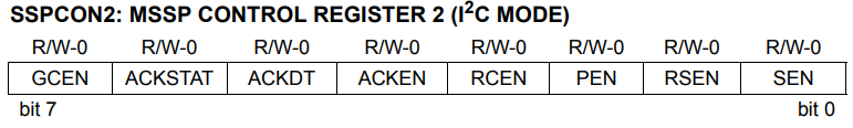
SEN: Start Condition or Stretch Enable bit. In master mode, setting this bit to initiate start condition on SCL & SDA pins and it will be automatically cleared by the hardware. And in slave mode setting this bit enables clock stretching for both slave receive and slave transmit. If it is cleared in slave mode, clock stretching is enabled only for slave transmit.
RSEN: Repeated start condition enable bit. This bit has application only in master mode. Setting this bit will initiate repeated start condition on both SCL & SDA pins and it will be cleared automatically in hardware.
PEN: Stop condition enable bit. This bit has application only in master mode. Setting this bit will initiate stop condition on both SCL & SDA pins and it will be automatically cleared in hardware.
RCEN: Receive enable bit. This bit also has application only in master mode. Setting this bit enables receive mode for I2C.
ACKEN: Acknowledge sequence enable bit. Setting this bit initiates acknowledge sequence on SCL & SDA lines and it will send ACKDT (see below) bit. This bit will be automatically cleared in hardware. It has application only in master receive mode.
ACKDT: Acknowledge data bit. 1 means not acknowledge and 0 means acknowledge. This value will be transmitted when we set the ACKEN bit (above). This bit has application only in master receive mode.
ACKSTAT: Acknowledge status bit. 1 indicates that acknowledgment was not received from the slave and vice versa. This bit has applications in master transmit mode only.
GCEN: General call enable bit. Setting this bit enables interrupt when a general call address is received in the register SSPSR.
Example Functions in programs:
//Wait function
void wait()
{
while(SSPIF==0)
SSPIF=0;
}
//Start condition
void I2C_start()
{
SEN=1; //Initially we made SSPCON as 0 then we should make it as 1
wait();
}
//stop condition
void I2C_stop()
{
PEN=1; //stop condition enable bit
wait();
}
//restart condition
void restart()
{
RSEN=1; //restart condition
wait();
}
void I2C_send(unsigned char send)
{
ACKTAT=1; //If ACKSTAT is 1 it shows that ask is not received from slave
SSPBUF=send; //send the data until it receives
while(ACKSTAT==1); //This shows hold until it receives the acknowlegdement
wait();
}
void read(unsigned char i)
{
unsigned char read;
if(i==2)
ACKDT=1; ; //Not Acknowledged
else
ACKDT=0; //Acknowledged
while(BF==0);
read=SSPBUF;
SSPCON=0;
SSPIF=0;
ACKEN=1;
return(read); //it clears the SDA and SDD automatically
}
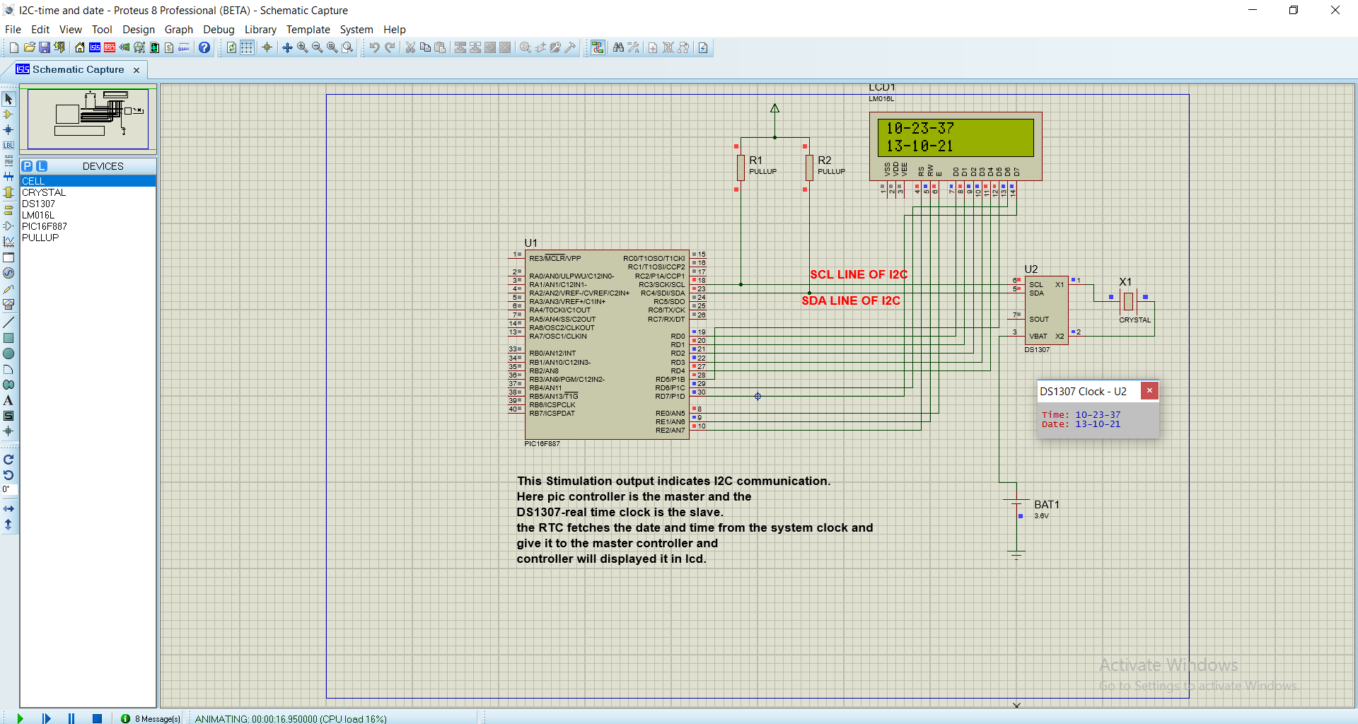
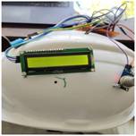
STIMULATION OUTPUT:
Advantages :
• Can be configured in multi-master mode.
• Complexity is reduced because it uses only 2 bi-directional lines (unlike SPI Communication).
• Cost-efficient..
• It uses ACK/NACK feature due to which it has improved error handling capabilities
Limitations :
• Slower speed.
• Half-duplex communication is used in the I2C communication protocol.


Comments
Crapersoft, well knowledged in Bigdata, datamining and iot working environment in coimbatore.
Replygot good website... with advanced technologies...
ReplyI have published my research paper to Scopus at short duration thanks to help of crapersoft.
Reply