AUTOMATION-->COMMUNICATION PROTOCOLS
SPI-SERIAL PHERIPHARAL INTERFACE
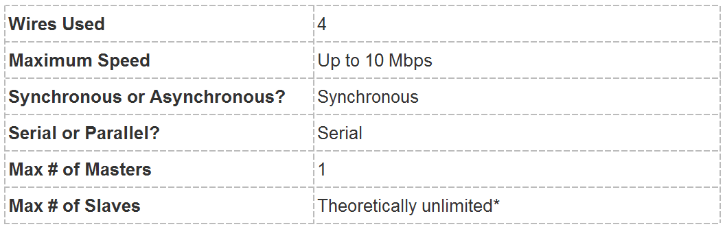
The Serial Peripheral Interface (SPI) is a synchronous serial communication interface specification used for short-distance communication, primarily in embedded systems. The interface was developed by Motorola in 1972. SPI provide a full duplex communication at very high speed. SPI is a master slave type protocol that provides a simple and low cost interface between a microcontroller and its peripherals.
SPI interface is available on popular communication cotrollers such as PIC,AVR and ARM controller,etc.
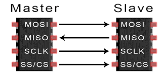
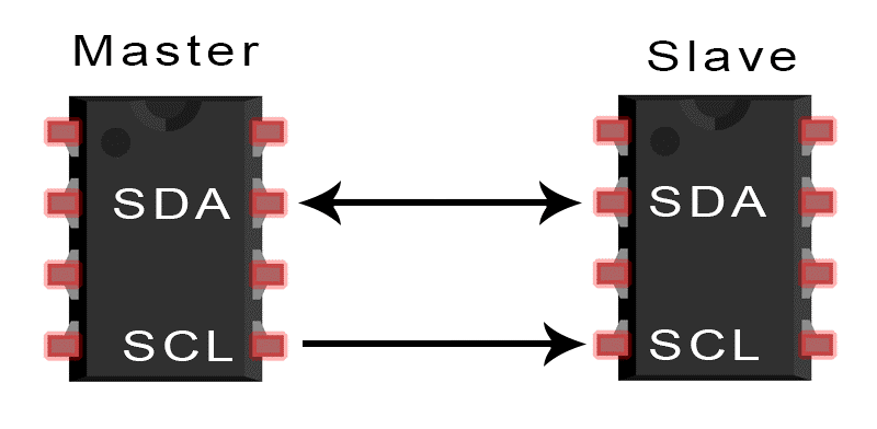
SPI protocol consists of four wires such as MISO, MOSI, CLK. SS used for master slave communication. The master is a microcontroller, and the slaves are other peripherals like sensors, GSM modem and GPS modem, etc. The multiple slaves are interfaced to the master through a SPI serial bus. The SPI protocol does not support the Multi-master communication and it is used for a short distance within a circuit board.
Serial Peripheral Interface Basics
SPI Lines:
MISO (Master in Slave out):The MISO line is configured as an input in a master device and as an output in a slave device.
MOSI (Master out Slave in):The MOSI is a line configured as an output in a master device and as an input in a slave device wherein it is used to synchronize the data movement.
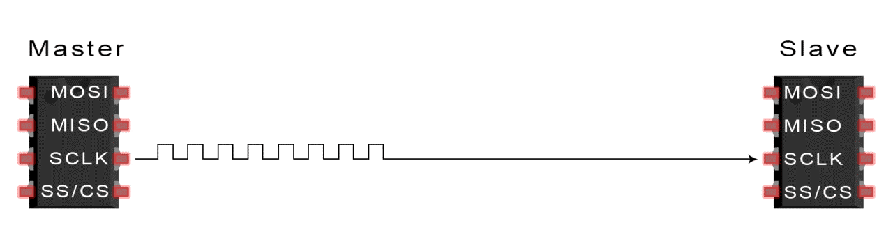
SCK (serial clock):This signal is always driven by the master for synchronous data transfer between the master and the slave. It is used to synchronize the data movement both in and out through the MOSI and MISO lines.There are two types of triggering mechanism in the clock signal.That are used to intimate the receiver about the data.
1.Edge triggering
2.Level triggering

The most commonly used triggering is edge triggering. they are two types,
1.Raising Edge (low to high transition on clock)
2.Falling Edge (high to low transition on clock)
Depends on how the receiver is configured on detecting the edge, the receiver will look for data on the data bus from the next bit.
SS (Slave Select) and CS (Chip Select): This signal is driven by the master to select individual slaves/Peripheral devices. It is an input line used to select the slave devices.
In SPI protocol, master slave communication with SPI serial bus is configured as,
1.Single Slave configuration
2.Independent Slave configuration
3.Daisy Chain configuration
SINGLE SLAVE CONFGURATION:
Here the communication is always initiated by the master.
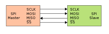
1.The master outputs the clock signal
2. The master switches the SS/CS pin to a low voltage state, which activates the slave
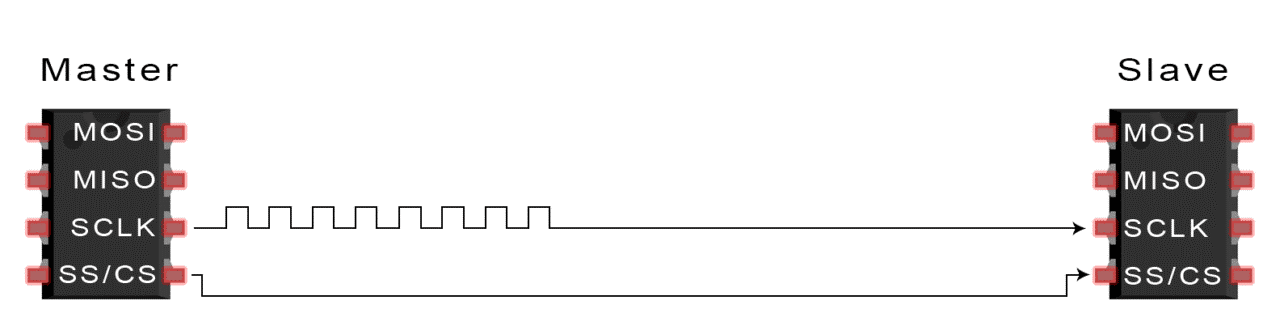
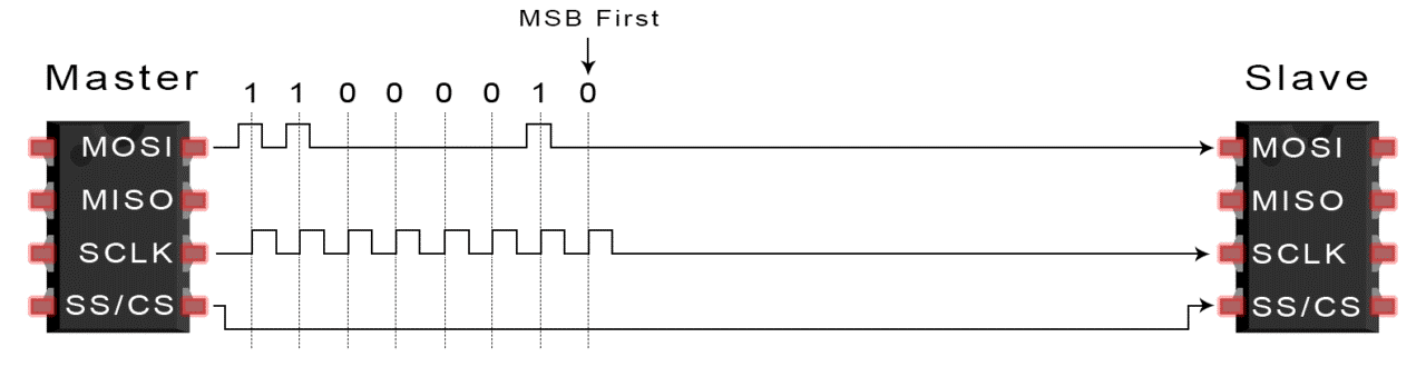
3.The master sends the data one bit at a time to the slave along the MOSI line. The slave reads the bits as they are received
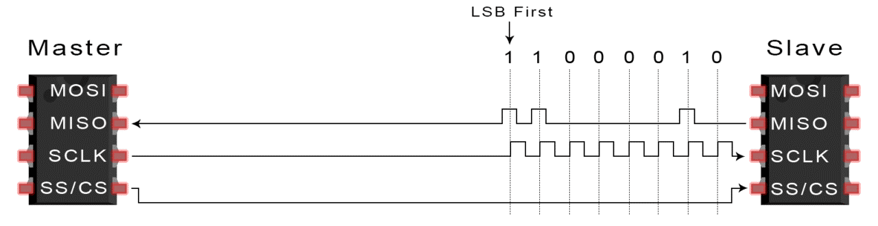
4. If a response is needed, the slave returns data one bit at a time to the master along the MISO line. The master reads the bits as they are received
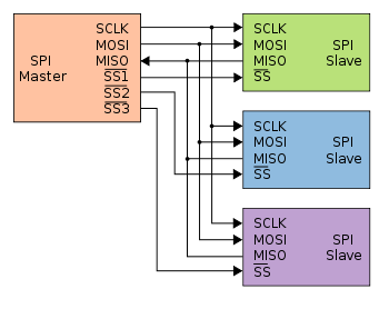
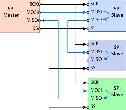
INDEPENDENT SLAVE CONFIGURATION:
This is a multiple slave configuration with one master and multiple slaves through the SPI serial bus. The multiple slaves are connected in parallel to the master device with the SPI serial bus. Here, all the clock lines and data lines are connected together, but the chip select pin from each slave device must be connected to a separate slave select pin on the maser device.The data transfer is organized by using the shift registers at both master and slave devices with a given word size of about 8-bit and 16-bit, respectively. Both the devices are connected in a ring form so that the maser shift register value is transmitted through the MOSI line, and then the slave shifts data in its shift register. The data is usually shifted out with the MSB first and shifting new LSB into the same register.
DAISY CHAIN CONFIGURATION:
In this configuration, only a single slave select line is connected to all the slaves. The MOSI of the master is connected to the MOSI of the slave1,The MISO of the slave 1 is connected to the MOSI of slave 2 and so on, The MISO pin of the final slave will get connected to the MISO pin of the master.
Significance Of Clock Polarity and Phase:
Generally, the transmission and reception of data is performed with respect to the clock pulses at rising edges and falling edges. The Advanced microcontrollers have two frequencies: internal frequency and external frequency. SPI peripherals could be added by sharing the MISO, MOSI and SCLK lines. The peripherals are of different types or speeds like ADC, DAC, etc. So we need to change the SPCR settings between the transfers to different peripherals.
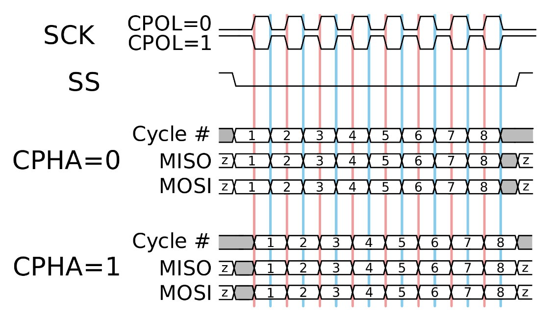
The SPI bus operates in one of the 4 different transfer modes with a clock polarity (CPOL) and clock phase (CPHA) which defines a clock format to be used. The clock polarity and the phase clock rates depend on which peripheral device you are trying to communicate with the master.
CPHA=0, CPOL=0:
The first bit starts as a lower signal - the data is sampled at rising edge and the data changes on falling edge.
CPHA=0 , CPOL=1:
The first bit starts with a lower clock - the data is sampled at falling edge and the data changes on rising edge.
CPHA=1 , CPOL=0:
The first bit starts with a higher clock - the data is sampled at falling edge. and the data changes on rising edge.
CPHA=1 , CPOL=1:
The first bit starts with a higher clock the data is sampled at rising edge, and the data changes on falling edge.
REGISTERS USED IN SPI :
SSPSTAT – MSSP Status Register
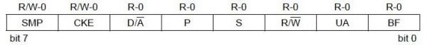
SSPSTAT Register MSSP Module PIC 16F877A
BF : This is the buffer full status bit. It is applicable only in receive mode and indicates that the data is ready to read. This bit is set once the data reception is complete and it is transferred from SSPSR to SSPBUF register.
UA : Update Address Bit. This bit is used only in I2C Mode. So please ignore it.
R/W : Read/Write information. This bit is used only in I2C Mode. So please ignore it.
S : Start Bit. This bit is used only in I2C Mode. So please ignore it.
P : Stop Bit. This bit is used only in I2C Mode. So please ignore it.
D/A : Data/Address bit. This bit is used only in I2C Mode. So please ignore it.
CKE : SPI Clock Edge Select. If this bit is 0, data transmission occurs on transition from idle to active clock state. And if it is 1, data transmission occurs on transition from active to idle clock state. Idle state means the status of the line when there is no data transfer, it can be LOW (0) or HIGH (1).
SMP : Sample bit.
Master Mode : If this bit is set 0, input data is sampled at the middle of the data output frame. And if it is set 1, input data is sampled at the end of data output frame.
Slave Mode : This bit must be set 0 in the slave mode.
SSPCON1 – MSSP Control Register 1
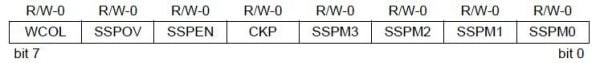
SSPCON1 Register MSSP Module PIC 16F877A
SSPM0 ~ SSPM3 : Synchronous Serial Port Mode Select
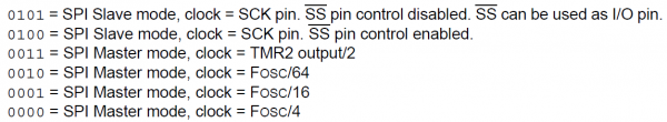
SSP Mode Select Bits
CKP : SPI Clock Polarity select bit. If this bit is 0, idle clock state will be LOW (0) and if it is 1, idle clock state will be HIGH (1).
SSPEN : Synchronous serial port enable. Setting this bit enables the MSSP module for using in SPI or I2C mode.
SSPOV : Receive overflow indicator bit.
Slave Mode : This bit is set when a new byte is received while SSPBUF is holding the previous data. In this case data in the SSPSR is lost. Overflow will only occur in slave mode. You have to read any previous data in the SSPBUF before transmitting data to avoid overflow. This bit must be cleared in the software.
<&nsbp>Master Mode :Overflow bit won’t set in master mode as each transmission/reception is initiated by writing to SSPBUF. Slave cannot push any data to Master. For reading data from slave device, master has to write some data (dummy) to the slave.
WCOL : Write collision detect bit. This flag is applicable only in transmit mode. It is set when the SSPBUF register is written while transmitting the previous word.
SSPBUF – MSSP – Buffer Register
All data read/write operations has to happen with this register. For example we can write a data to this register to transmitting it to slave devices and we can read the received data from this register.
Example Functions in Programs:
//For Master
void trans(char a)
{
SSPBUF=a;
while(SSPIF==0)
{
SSPIF=0;
}}
//For Slave
void receive(char b)
{
while(SSPIF==0)
{
b=SSPBUF;
}
}
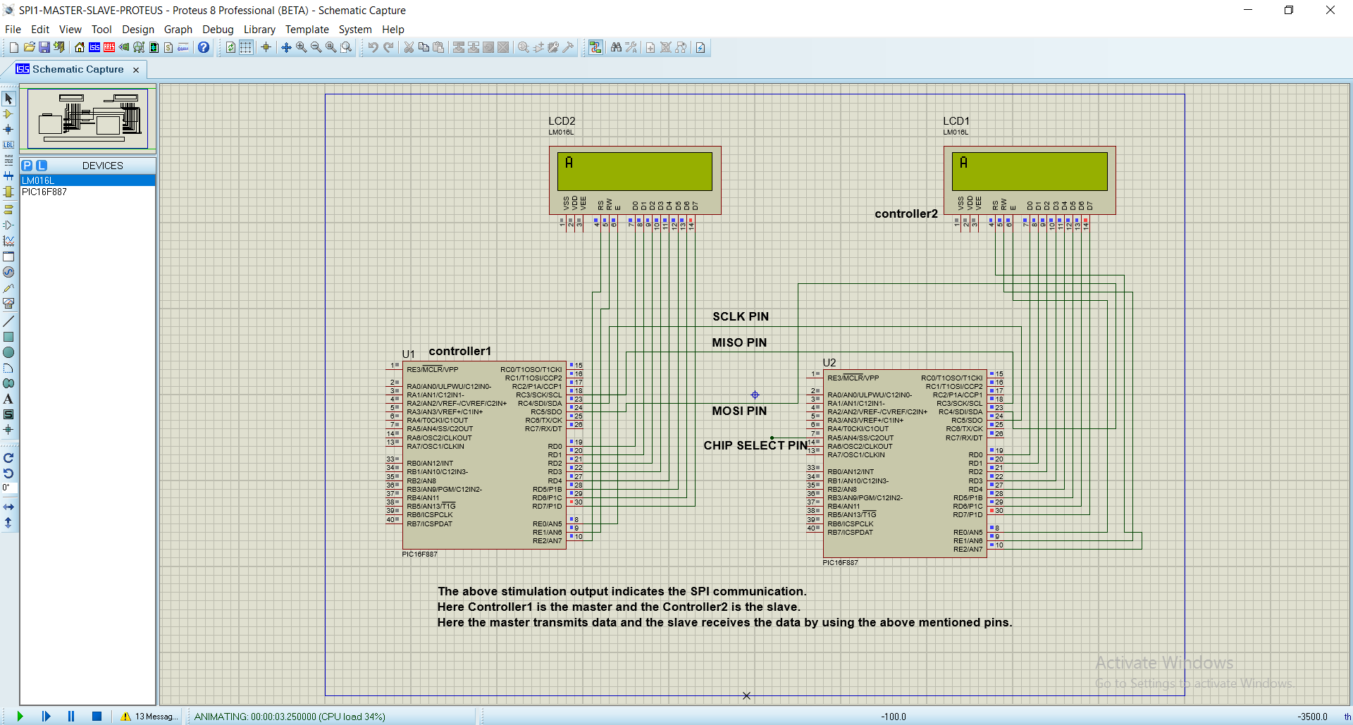
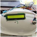
STIMULATION OUTPUT:
Applications of SPI
1.Memory: SD Card , MMC , EEPROM , Flash.
2.Sensors: Temperature and Pressure.
3.Control Devices: ADC , DAC , digital POTS and Audio Codec.
4.Others: Camera Lens Mount, touchscreen, LCD, RTC, video game controller, etc.
Advantages of using SPI
1.The protocol is simple as there is no complicated slave addressing system like I2C.
2.It is the fastest protocol compared to UART and I2C.
3.No start and stop bits unlike UART which means data can be transmitted continuously without interruption.
4.Separate MISO and MOSI lines, so data can be sent and received at the same time
Disadvantage of using SPI
1.Uses four wires (I2C and UARTs use two)
2.No acknowledgement that the data has been successfully received (I2C has this)
3.No form of error checking like the parity bit in UART
4.Only allows for a single master


Comments
Crapersoft, well knowledged in Bigdata, datamining and iot working environment in coimbatore.
Replygot good website... with advanced technologies...
ReplyI have published my research paper to Scopus at short duration thanks to help of crapersoft.
Reply